
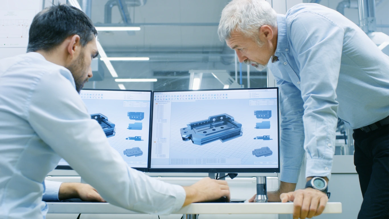
Imagine ordering a hundred custom parts, waiting weeks for them to arrive, and then discovering that none of them fit together properly. Every dimension on the drawing was technically correct, yet the assembly fails. Parts wobble, holes do not line up, and components that should slide together bind instead. This is one of the most frustrating and expensive problems in manufacturing, and it happens more often than you might think.
The cause is almost always the same. The drawing told the machinist what size to make each part, but it never clearly defined how those parts needed to relate to one another. That is exactly the problem Geometric Dimensioning and Tolerancing, or GD&T, was created to solve. In this guide, we break down what GD&T is, why it matters, and how it can make or break your manufacturing results.
What Is GD&T?
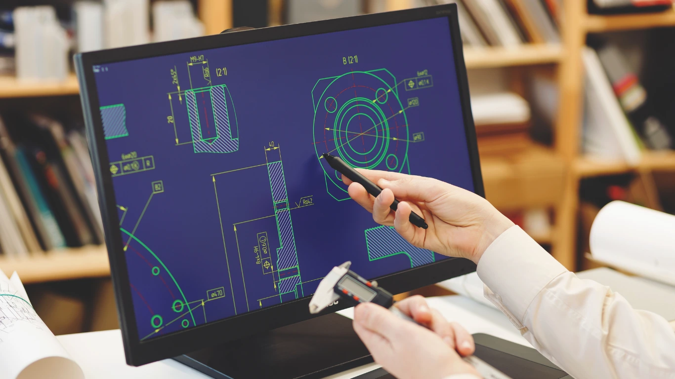
GD&T is a standardized language of symbols used on engineering drawings to define the size, shape, orientation, and location of every feature on a part. Instead of relying on basic dimensions alone, it precisely communicates how much variation is acceptable and how each feature must relate to the others.
Think of it this way. A traditional dimension might say a hole must be 50 millimeters from an edge, give or take a small tolerance. GD&T goes further. It defines not just the distance, but also how round the hole must be, how straight, how perpendicular to the surface, and how it relates to the other critical features on the part. It removes ambiguity and makes sure everyone reading the drawing understands exactly what a good part looks like.
Why Basic Dimensions Are Not Enough
Traditional dimensioning has a hidden weakness. It treats each measurement in isolation, which leaves room for interpretation. Two machinists can read the same drawing, make parts that both pass inspection on paper, and still end up with components that will not assemble.
The reason is that real parts are never perfect. Every surface has slight variations, every hole is a little off from ideal, and every edge has some deviation. Basic dimensions do not fully control how these small imperfections stack up across a part. GD&T does. It defines the relationships between features, so the small variations that are unavoidable in manufacturing never add up to a part that fails to work.
For any Mechanical Designer, this distinction is the difference between a drawing that produces working parts and one that produces expensive scrap.
How GD&T Makes or Breaks Your Manufacturing
The impact of GD&T runs through every stage of production. Get it right and everything downstream runs smoothly. Get it wrong, and the problems multiply fast.
- Assembly success. Parts defined with proper GD&T fit together as intended, every time, even when made by different suppliers or at different times.
- Lower costs. Clear tolerances mean fewer rejected parts, less rework, and less wasted material. You only pay for the precision you actually need.
- Faster production. When a drawing removes all guesswork, machinists and inspectors work with confidence instead of stopping to ask questions or make assumptions.
- Better supplier communication. GD&T is an international standard, so a drawing means the same thing to a shop across town or across the world.
- Reliable quality. Inspection becomes straightforward because the drawing clearly defines what passes and what does not.
Poor tolerancing does the opposite. It creates confusion, drives up costs, delays projects, and produces parts that do not perform. The quality of your GD&T often determines the quality of your entire manufacturing outcome.
The Role of Tolerancing in Mechanical Design
Here is where experience truly matters. Applying GD&T well is not about adding as many symbols as possible. It is about applying the right controls in the right places, and that requires deep engineering judgment.
Good Mechanical Design uses tolerancing strategically. Tight tolerances cost more to manufacture and inspect, so applying them everywhere wastes money. Loose tolerances save cost but risk parts that do not function. The skill lies in knowing exactly which features are critical to how the part works and which have room to spare. A well-toleranced drawing is tight where it counts and generous where it can afford to be.
This balance is one of the clearest signs of thoughtful design. It protects the function of the part while keeping manufacturing efficient and affordable. Done right, it delivers quality without overspending on precision you do not need.
Why You Need a Skilled Mechanical Design Engineer for GD&T
GD&T is powerful, but it is also easy to get wrong. Misapplied symbols, missing datums, or tolerances that do not reflect how a part actually functions can cause the very problems the system is meant to prevent. This is why the person creating your drawings matters so much.
An experienced Mechanical Design engineer understands not just the symbols, but the reasoning behind them. They know how a part will be manufactured, how it will be measured, and how it must perform in the real world. That knowledge shapes every tolerance decision. They identify the features that are truly critical, define clear datums that reflect how the part is used, and apply controls that make the part both functional and manufacturable.
The result is a drawing that communicates perfectly with your suppliers and produces parts that work the first time. In a field where a single misunderstood tolerance can scrap an entire production run, that expertise pays for itself quickly.
Common GD&T Mistakes That Cost You Money
Even well-intentioned drawings can go wrong. Here are the errors that most often lead to failed parts and blown budgets:
- Applying tight tolerances everywhere, which drives up cost without improving function
- Missing or poorly chosen datums that leave critical relationships undefined
- Tolerances that do not reflect how the part is actually assembled or used
- Inconsistent standards that confuse suppliers and inspectors
- Drawings so cluttered with controls that the truly important ones get lost
Avoiding these mistakes starts with putting your designs in the hands of engineers who apply GD&T with real understanding.
Get GD&T Right With CustoMachinery
Precision parts start with precise drawings. When your engineering documentation communicates clearly and applies tolerances intelligently, manufacturing becomes faster, cheaper, and far more reliable. When it does not, you pay for it in scrap, delays, and parts that never quite work.
At CustoMachinery, we bring over 22 years of engineering experience to every drawing we produce. Our team applies GD&T with the judgment that only comes from years of designing real machinery, tight where your parts demand it and efficient everywhere else. The result is documentation your suppliers understand and parts that fit and function exactly as intended.
If you are struggling with parts that do not assemble, suppliers who misread your drawings, or costs that keep climbing, we can help. Contact CustoMachinery today to make sure your next project is defined right from the start and built to work the first time.
Frequently Asked Questions
What does GD&T stand for?
It stands for Geometric Dimensioning and Tolerancing, a standardized system of symbols that defines the size, shape, orientation, and location of features on engineering drawings.
Why is GD&T better than standard dimensioning?
It controls how features relate to one another, not just their individual sizes, so the small variations in manufacturing never add up to a part that fails to assemble or function.
Do I always need tight tolerances on my parts?
No. Tight tolerances raise cost, so a skilled Mechanical Designer applies them only where a part’s function requires it and keeps other features looser to save money.